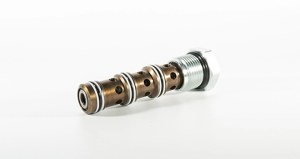
A hydraulic priority flow divider/combiner is a specialized valve used in hydraulic systems to divide or combine hydraulic fluid flow. It is designed as a compact cartridge-style valve that can be easily installed within a hydraulic manifold or valve block. The flow divider function allows the hydraulic fluid to be divided into multiple outlets, distributing the flow evenly among the branches. This is useful in applications where hydraulic power needs to be supplied to multiple actuators or components simultaneously.
What Is A Flow Divider Combiner?
A flow combiner valve is a hydraulic device that performs the dual function of splitting or combining hydraulic fluid flow. It is designed to divide an incoming flow into multiple equal or proportionate streams or combine multiple flows into a single output. The device consists of an input port where the hydraulic fluid enters and multiple output ports where the divided or combined flows are directed. Inside the flow divider combiner, various mechanisms like spools, gears, or pistons are utilized to regulate the flow distribution or combination. In flow divider mode, the device evenly splits the incoming flow into two or more output streams, ensuring each stream receives an equal or predetermined proportion of the total flow. This is valuable in applications requiring precise flow distribution, such as synchronizing parallel hydraulic cylinders. In flow combiner mode, the device merges multiple incoming flows from different sources into a single output flow, beneficial for coordinating multiple hydraulic actuators simultaneously, such as in lifting or pressing operations. With its capabilities, the flow divider combiner enables efficient control and operation of hydraulic systems with multiple actuators or branches.
How Does Hydraulic Flow Splitter Work?
A hydraulic flow splitter, also known as a flow diverter hydraulic, is a device used in hydraulic systems to divide a single input flow of hydraulic fluid into multiple output flows, while maintaining a consistent ratio between the outputs. This device is essential in various hydraulic applications where precise control of multiple hydraulic actuators or functions is required. Let's take a look how hydraulic flow dividers work.
Input Flow: The hydraulic flow splitter valve is connected to a single source of hydraulic fluid, usually a pump or another hydraulic power source. This input flow carries pressurized hydraulic fluid that needs to be distributed to multiple hydraulic circuits or components.
Internal Mechanism: Inside the hydraulic flow splitter, there are typically precision-engineered components such as gears, spools, or rotary valves. The specific design may vary depending on the type of flow splitter being used.
Flow Division: As the hydraulic fluid enters the flow splitter, the internal mechanism divides the flow into multiple separate paths, leading to the output ports. The key feature of a hydraulic flow splitter is that it distributes the flow in a consistent ratio among the output ports. For example, if you have a 50/50 hydraulic flow splitter, it will ensure that each output port receives half of the input flow.
Proportional Control: Hydraulic flow splitters often allow for adjustment of the flow distribution ratio. This can be achieved by changing the position of the internal mechanism or by using flow control valves in each output line. This feature provides flexibility in controlling the speed or force of hydraulic actuators connected to the output ports.
Pressure Compensation: Many hydraulic flow splitters incorporate pressure compensation mechanisms to ensure that each output port receives the same pressure, even if the load on the hydraulic system varies. This helps maintain consistent performance of hydraulic components connected to the splitter.
Applications: Hydraulic flow splitters are used in a wide range of applications, including agriculture (to control multiple hydraulic cylinders on farming equipment), construction machinery (to synchronize the movement of multiple hydraulic actuators), and industrial automation (to control multiple functions in manufacturing processes).
2 Way, 3 Way, 4 Way Flow Divider
2-Way Flow Divider:
Number of Output Ports: A 2-way flow divider has two output ports.
Flow Distribution: In a 2-way flow divider, the input flow is divided into two equal output flows. Each output port receives half of the input flow. This is often referred to as a 50/50 flow distribution.
Common applications for hydraulic 2 way flow dividers include scenarios where you need to control two hydraulic cylinders or actuators with equal force or speed, such as in some agricultural equipment or industrial machinery.
3-Way Flow Divider:
Number of Output Ports: A 3 way hydraulic flow divider has three output ports.
Flow Distribution: In a 3-way flow divider, the input flow is divided into three output flows. The flow distribution is typically equal, with each output port receiving one-third of the input flow, resulting in a 33/33/33 distribution.
3-way flow dividers are commonly used in applications where you need to control three hydraulic cylinders or actuators with equal flow, such as in some material handling equipment or hydraulic presses.
4-Way Flow Divider:
Number of Output Ports: A 4 way hydraulic flow divider has four output ports.
Flow Distribution: In a 4-way flow divider, the input flow is divided into four equal output flows. Each output port receives one-fourth of the input flow, resulting in a 25/25/25/25 distribution.
4-way flow dividers are used when you need to control four hydraulic cylinders or actuators with equal flow, often seen in applications like certain types of construction machinery, where synchronization of multiple functions is required.
Hydraulic Flow Divider Gear Type VS Cartridge-type
Gear-Type Hydraulic Flow Divider:
Design: Gear-type hydraulic flow dividers use precision-engineered gears to divide the input flow into multiple output flows. The gear sizes and arrangement determine the flow distribution ratio.
Flow Distribution: Gear-type dividers typically provide fixed flow distribution ratios that are set during manufacturing. These ratios can be adjusted by changing the gear sizes or positions, but this often requires disassembling the unit.
Flexibility: They offer limited flexibility in changing the flow distribution ratio on the fly and may require manual adjustments.
Applications: Gear-type flow dividers are commonly used in applications where a consistent and fixed flow ratio is sufficient, such as in some industrial machinery and construction equipment.
Maintenance: Maintenance of gear-type flow dividers involves regular inspection, lubrication, and possible replacement of gears or components if wear occurs.
Cartridge-Type Hydraulic Flow Divider:
Design: Cartridge-type hydraulic flow dividers use modular cartridges that can be easily inserted or removed from a manifold block. Each cartridge typically contains flow control elements, such as spools or orifices.
Flow Distribution: Cartridge-type dividers offer greater flexibility in adjusting the flow distribution ratio because cartridges with different flow control elements can be swapped in and out of the manifold block.
Flexibility: They allow for on-the-fly adjustments of flow distribution ratios without the need for disassembly. This makes them suitable for applications where dynamic control is required.
Applications: Cartridge-type flow dividers are often used in applications where the flow distribution needs to be adaptable, such as in mobile hydraulic systems, forestry equipment, and agricultural machinery.
Maintenance: Maintenance of cartridge-type flow dividers mainly involves inspecting and replacing cartridges as needed. This can be done without disassembling the entire unit.
As one of hydraulic cartridge valve manufacturers, we can offer sorts of related products for sale, if you are interested, please leave us a message.
Localisation : No. 03, 03rd Kechuang Road, Xinwu Economic Development Zone, Wanzhi District, Wuhu City, Anhui Province, China, 241100 Wuhu,
Personne à contacter : Xu William, 0553 8812880


